Pm-90 Pump Installation
- UNPACKING
- IDENTIFICATION OF PARTS
- LOCATION IN THE LAB
- POWER REQUIREMENTS
- FLUID CONNECTIONS
- COMMUNICATIONS
UNPACKING
Please retain the shipping box and packing materials until the unit has been fully tested. The shipping materials will be needed if you discover damage incurred during shipping.
The shipping box should contain the following items:
- PM-92 or PM-91 Pump
- PM-90 Accessories (includes: power cord, 1/8" PTFE inlet lines with fittings, 60 mL syringe, luer adapter).
- Pulse Damper (PM-91 ONLY)
If any discrepancies exist, retain the packing slip and contact BASi Customer Service for assistance.
IDENTIFICATION OF PARTS
The following figures show front and back views of the PM-92 and PM-91 pumps. The parts identified by number are described below.
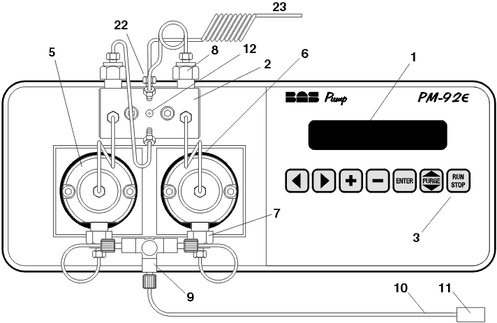
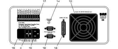
| 1. | LCD display | 12. | Purge port |
| 2. | Pressure manifold | 13. | Air filter |
| 3. | Keyboard | 14. | Pressure offset adjustment |
| 4. | POWER switch | 15. | Power input |
| 5. | Pump head | 16. | Fuse |
| 6. | Plunger-irrigation port | 17. | Terminal strip |
| 7. | Inlet check-valve assembly | 18. | Serial RS-232c connector |
| 8. | Outlet check-valve assembly | 19. | BAS Communication Network connector |
| 9. | Inlet tee (PM-92) | 20. | Inlet fitting (PM-91) |
| 10. | Solvent-uptake line | 21. | Pulse Damper (PM-91) |
| 11. | Solvent-uptake frit | 22. | Outlet to injector |
| 23. | Mixing tube (PM-92) |
LOCATION IN THE LAB
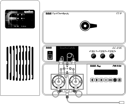
The PM-90 pump is designed to serve as the base for a stack of BASi chromatography instruments. A typical setup is illustrated by the BAS-502e chromatograph. The components of this system are the PM-92 pump, LC-22C temperature controller, and CC-5 flowcell compartment. The epsilon LC detector is on the left.
Location considerations for the pump must, of necessity, include the requirements for all the component instruments in the stack. Use the following guidelines:
- Provide a surge-free power source which can be dedicated to the chromatograph. Other laboratory instruments such as ovens, vortex mixers, centrifuges, and large motors may cause spikes in the power supply.
- Ensure that all components of the chromatograph share the same ground circuit. This can best be accomplished by plugging all components into a multi-outlet power strip. Plugging the components into independent outlets can produce ground loops (current that flows between ground circuits at slightly different potentials) which can produce baseline noise.
- Locate the chromatograph on a stable bench. Vibrations can hamper the performance of any sensitive instrument.
- Select a room where temperature remains stable throughout the day. Avoid installing the chromatograph near windows, air ducts, ovens, or refrigerators.
- Place the chromatograph away from busy, congested areas. Remote, isolated areas are best for high-sensitivity work.
- Avoid very dry areas and areas that are carpeted. Static electricity can affect instrument performance. Anti-static floor mats and bench mats are useful if spiking caused by static charge is a problem.
- Avoid areas where radio-frequency interference is likely. Beeper-type paging devices can be a problem in some installations.
POWER REQUIREMENTS
The power cord attaches to the PM-90 via the receptacle on the rear of the instrument. The pump can be operated with either 100, 120, 220, or 240 VAC and 50 or 60 Hz power. The instrument uses a fused self-sensing power supply. There is no need to make power related adjustments. You should check to see that the fuse is the proper rating for the voltage used:
| Voltage | Fuse |
| 100-120V | 2.0 Amp Slow Blow |
| 220-240V | 1.0 Amp Slow Blow |
FLUID CONNECTIONS
PM-92
The PM-92 is factory plumbed, and ready as received for final connection of the inlet and outlet solvent lines. Unwrap the PTFE tubing carefully and remove the protective cover from the solvent-uptake frit. The uptake tubing connects to the tee at the PM-92 pump head with a flangeless fitting. Be sure to install this with the flat face of the ferrule entering the tee:
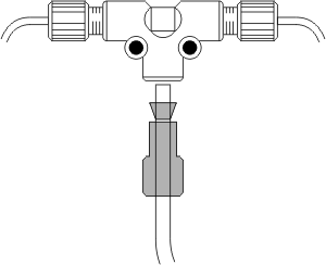
Connect the mixing tube (#23) to the topmost pump manifold outlet (#22) with the nut and ferrule provided. Connect the other end of the mixing tube to an in-line filter assembly (MR-4135). Then connect the filter to the input of your injection valve. We recommend 1/16" OD, 0.015" ID, #316 stainless steel tubing for these connections. We strongly recommend using plastic fittings (MF-4166) to connect the in-line filter, as this is a frequently opened connection. Plastic fittings can be replaced when they start to leak; leaks in steel fittings require the replacement of the entire tube.
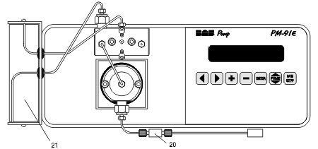
PM-91
Unwrap the teflon tubing carefully and remove the protective cover from the solvent-uptake frit. The uptake tubing connects to the inlet fitting (#20) at the PM-91 pump head with a flangeless fitting. Be sure to install this with the flat face of the ferrule entering the inline fitting.
Mount the pulse damper (#21) to the left side of the pump cover using the two 6-32 flat head screws supplied. To ensure that any air bubbles that enter the system don't get trapped in the pulse damper, always have the flow from the pump (emerging from the upper check valve) enter the bottom of the pulse damper and emerge from the top.
Connect the bottom line of the pulse damper to the outlet check valve assembly. Connect the top line of the pulse damper to the second highest port on the pressure manifold. The topmost port (#22) should be connected to an in-line filter assembly (MR-4135). Then connect the filter to the input of your injection valve. We recommend 1/16" OD, 0.015" ID, #316 stainless steel tubing for these connections. We strongly recommend using plastic fittings (MF-4166) to connect the in-line filter, as this is a frequently opened connection. Plastic fittings can be replaced when they start to leak; leaks in steel fittings require the replacement of the entire tube.
Installation is now complete. Refer to the STARTUP section to begin purging the pump.
COMMUNICATIONS
Communication with other instruments is accomplished via connections to the rear panel:
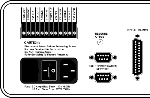
The only connection that needs to be made to an epsilon system is via a BAS COMMUNICATION NETWORK port. Insert the female end of the 9-pin cable provided into either port. The other end of this cable is connected to the PUMP connector on the rear panel of the epsilon controller (or the COMM. NET connector on a DA-5 Data System). This connection needs to be made only if you wish to control the pump from the computer. Many users prefer to control the pump from its front panel (see the section on Manual Controls).
Additional connections are provided for other applications:
PRESSURE OFFSET. This potentiometer is used to adjust pen position when recording pump pressure.
To monitor pressure with an epsilon system, connect the 'PRESS.' terminal and its 'GND' as an external detector with a 10V input. Click here for details.
To monitor pump pressure with a chart recorder, first set your chart recorder for an input of 10 V. Connect two wires from the PRESS. and GND connectors on the terminal strip of the PM-90 to the input of the chart recorder. Adjust the PRESSURE OFFSET potentiometer on the rear panel of the PM-90 until the chart-recorder pen is about mid-scale. Now reduce the input voltage of the chart recorder in steps, adjusting the PRESSURE OFFSET control as necessary to keep the pen on the chart. Reduce the input voltage of the chart recorder until the pressure fluctuations can be measured on the chart (a 0.1 V input range should be about right). The analog pressure output produces 1 volt per 1000 PSI. The chart can be calibrated with the following formula:
SERIAL RS-232C. This 25-pin 'D' connector is provided for remote control of the PM-90 pump. In most cases, however, the pump is connect to the epsilon detector (or the DA-5 Data System) via one of the BAS COMMUNICATIONS NETWORK ports.
-
-
P = (1000 x D x V) / W
where:
-
P = pressure fluctuation in PSI
W = width of chart paper (mm)
D = magnitude of pen deflection (mm)
V = input range of chart recorder (Volts)